

LEM pioneers current sensing and develops digital output transducers with a sigma-delta bit stream interface (Subtitle)
By: Pascal Maeder (Global Product Manager, Drives/Welding)
Sources: David Jobling (ASIC Development Group Manager)
Stéphane Rollier (Product & Marcom Manager)
Mathieu Béguin (Marketing Engineer)
Why do current transducers go digital?
A couple of years ago, LEM’s Sales & Marketing observed the first signs of a technological turnaround: some of the leading OEMs (Original Equipment Manufacturers) in the servo-drives and robot industry were thinking of abandoning analog interfaces on their systems.
This change was driven by the evolution of controllers: the “brains of the machines”. The controllers function fully digitally internally and generally only had A/D’s (analog-to-digital converters) on their interfaces. This is no longer the case today; the A/D’s are disappearing in new controllers and customers are now asking for current transducers with a digital output so that they can easily connect to their new micro-controllers. Another advantage of a digital interface is that it is less sensitive to electro-magnetic interference.
Defining and developing products based on a new technology is complex and long: you cannot afford to get it wrong. After a comprehensive market survey conducted in 2013 by LEM’s marketing & product management teams, the R&D department started developing a Hall-based open-loop ASIC. The analog to digital (A/D) conversion is performed by an on-board sigma-delta modulator, giving a 1-bit serial bit stream output, with a sigma-delta modulator at the output.
The first prototype transducers were delivered to “alpha customers” at the end of 2015. The initial feedback was positive and LEM presented these future products at the PCIM tradeshow 2016 in Nuremberg, where more users showed interest in using this new technology.
The products
LEM proposed a range of digital output versions of the successful HO and HLSR open-loop Hall effect current transducers. These new components are for nominal current measurements of 10, 32, 50, 80, 100, 120, 150, 200, 250 ARMS in 3 different mechanical designs (PCB and panel mounting) and provide up to 12 bit resolution with 20 kHz bandwidth. The single-bit output minimizes the connections required, enabling highly compact transducers, and the digital output allows the user to choose the filter used on the bitstream to optimize between resolution and response time, according to the application. Digital outputs are also intrinsically immune to noise in hostile environments.

Fig.1: HLSR 50-PW, the digital version of LEM’s successful HLSR 50-P transducer (analog output).
The digital interface
The transducer output is a bit stream where the density of 1’s depends on the current measured, as illustrated in figure 2.
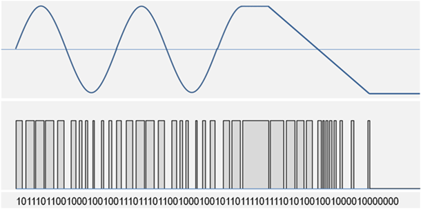
Fig.2: The digital conversion with a ∑Δ Modulator.
The detail of the transfer function is shown in figure 3. This shows the average density of 1’s on a scale from 0 to 1, and the same output if it is filtered and represented as a 16-bit word on a scale from 0 to 65’535 (decimal). See the next section for more on filtering options. Figure 3 also shows the equivalent output from an analog sensor. As with the analog sensor the performance of the new sensor is over the range +/-IPM, corresponding to an average density of 1’s from 0.1 to 0.9.

Figure 3: Transfer function.
The digital filter is implemented by the user, see figure 4. The advantage is that the number of connections to the transducer is minimized; each user can decide the filter(s) best suited to the application and the output format can be selected to match the system requirements.
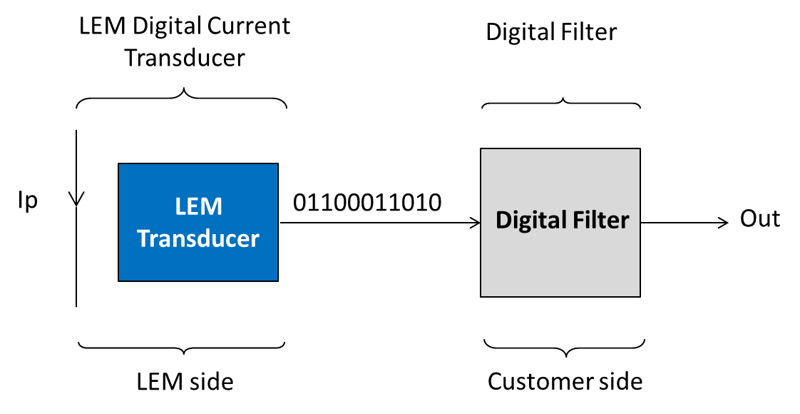
Figure 4: LEM provides a bit stream output.
Performances and filter choices
Any conversion from an analog to a digital signal involves quantization, and the error between the digital signal and the exact value of the analog signal it represents is equivalent to the addition of noise. The output from a sigma-delta modulator is more than simply a bitstream with a certain density of 1’s and 0’s; the sequence is randomized in a way that pushes the quantization noise out of band to frequencies higher than those of interest for current measurement. The user processes the bitstream in a digital filter which rejects the high frequency noise. As with any filter, compromises are made to optimize system performance: a narrow bandwidth gives lowest noise (or highest resolution) at the expense of response time, and vice versa. In the example of figure 5 the bitstream is processed twice: in a 20 kHz filter which gives a resolution of 12 bits for accurate measurement of the primary current and in a wideband filter to detect excess currents with a response time of 5μs. Additionally the transducer internal OCD (over current detect) output allows detection of short circuits with a response time of only 2.7 µs.
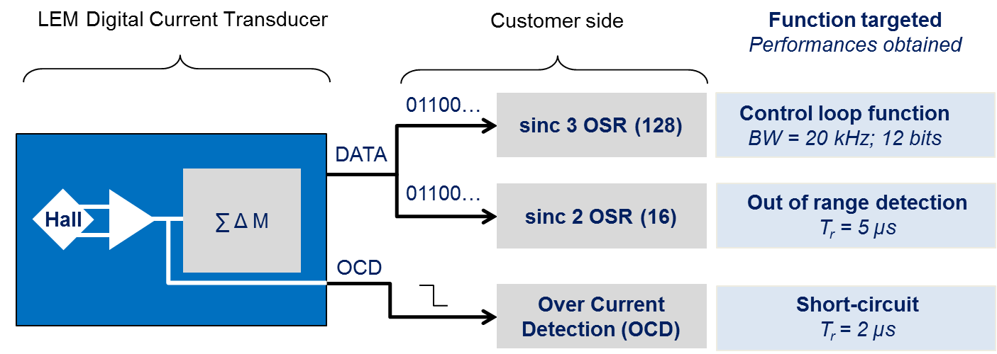
Figure 5: Application example with OSR and filter order influence on response time and resolution.
Bits are processed one at a time in the digital filter. Due to the modulator oversampling ratio (OSR), the digital filter output can be processed every OSR bits with no loss of information within the band of interest.
The latency of filter depends on its very nature: output is delayed by 2 x OSR x CLK period for a sinc2 whereas 3 x OSR x CLK period are needed to get the exact output after a step response with the very common sinc3 filter. The bit rate at the output of LEM’s new sensors is 10 Mb/s. The combination of OSR, filter choice and bit rate leads to the response time, the bandwidth and the effective resolution of each of the signal paths connected to the bitstream, as shown in figure 6 of the HO 150-NPW performance.
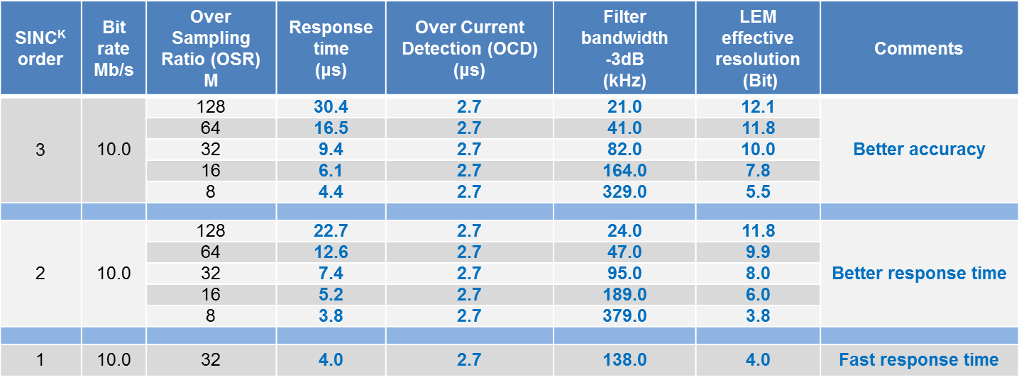
Figure 6: HO 150-NPW performances: Performances = f (OSR, SINC K FILTER, BANDWIDTH).
The resolution of the complete system including the analog part of the transducer, the sigma-delta modulator and the digital filter is limited either by the quantization noise inherent to the system or by the analog noise from the Hall cells and amplifiers. For fast response times (for example with an OSR of 16 and a sinc2 filter) the resolution is defined by the system and will be the same with any transducer. If the filter is changed to sinc3 and the OSR is increased the effective resolution is improved but will be limited to 11 – 13 bits (depending on the sensor sensitivity) by analog noise. The term “Effective” resolution is used because for system convenience the filter may output a word with a length of 16 bits or 2 x 8 bits. However only the most significant bits corresponding to the effective resolution contain useful information, the less significant bits contain noise.
Usually the digital filter output is sampled at a frequency equal to the bit rate divided by the OSR; this is referred to as decimation. With the LEM sensors if the OSR is 64 the output is updated every 6.4 us.
Physical interfaces
To transmit the bitstream LEM offers the choice between two physical interfaces. In both cases the bit rate is 10 Mb/s.
CMOS Single-ended
With the first, clock and data are provided as single-ended CMOS levels (Uc and GND). This is suitable for transmission over short distances, up to some 10’s of centimeters, after which EMC issues may become important. The maximum allowed capacitive load is 30 pF. The transducer pin allocation and timing diagram are shown in figures 7-8.
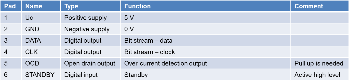
Figure 7: Single-Ended CMOS levels wiring.

Figure 8: Single-ended output (CMOS levels).
Manchester RS422
The second interface is suitable for transmission over longer distances. In this case the clock and data are combined as a Manchester coded signal. This is output on transducer pin 3 and its complement on pin 4. The differential signal thus generated is compatible with the RS422 standard. By keeping the two signal tracks physically close, EMC effects, both transmitted and received, can be kept to a low level. The pin allocation and timing diagrams are shown in figures 9-10.
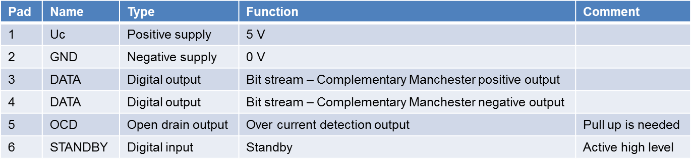
Figure 9: Manchester interfaces wiring.

Figure 10: Manchester transmissions data.
Conclusion
This technological leap is not “just a new family of transducers” for LEM and the industry.
The outlook for digital output transducers is very encouraging: customer feedback shows that a significant part of the market will shift to digital interfaces, starting with the high-end servo drives. We expect more industry segments to follow this trend. Our industry is going digital and LEM is leading the way!