

Technology innovations take fluxgate current transducers to previously unattainable performance levels.
The use of fluxgate technology in transducers for precise current measurement is well-known. In order to improve performance beyond that of existing sensors new ideas are needed. This article starts with a short overview of fluxgate-based current transducers, and then it shows how applying innovations to this architecture has allowed the development of a new family of transducers. Several related improvements must be made together, and the result is a compact transducer which maintains its accuracy over a wider temperature range and has a reduced noise level. The improved performance parameters and some key results of the product characterization will be presented.
Introduction to fluxgate current transducers.
The fluxgate current transducers described in this article are closed loop devices in which the magnetic field created in a magnetic circuit by the measured or primary current, IP, is exactly cancelled by a secondary or compensation current, Icomp, passed in a coil of Ncomp turns around the same magnetic circuit. In the general case where the primary current may have Np turns, IP is simply given by:
IP = Icomp x Ncomp / Np
The zero-field condition is detected by a fluxgate, which consists of a coil wound around a ferromagnetic core that saturates in the presence of a magnetic field. The inductance of the coil reduces when the core saturates. If a symmetrical square-wave voltage drives the fluxgate the rate of change of its current will increase when it saturates but the current waveform will be symmetrical unless a magnetic field due to the primary current is additionally applied, in which case the waveform will be asymmetric.

Figure 1. (a) Fluxgate drive waveform; (b,c) Fluxgate current in the absence and presence of an external magnetic field.
This is shown in figure 1: trace (a) shows a square applied voltage waveform, which has only odd harmonics of the fundamental frequency; trace (b) is the symmetrical current waveform obtained when the external magnetic field is zero; it also has only odd harmonics; trace (c) shows an asymmetric waveform when the external field is not zero; this waveform contains even harmonics and a DC component.
Figure 2 shows the operating principle of a current transducer using this principle. The square wave voltage is applied to the fluxgate with the H-Bridge; its current is converted to a voltage by resistance R, and its symmetry is measured by a signal treatment such as detecting the second harmonic of this waveform. The loop is completed by driving the compensation current with the Class AB amplifier such that this second harmonic is zero. Icomp is converted to a voltage by Rm.

Figure 2. Operating principle of a fluxgate transducer.
Note that the fluxgate system covers the DC and low frequency range of the primary current; for higher frequencies the current transformer effect is used directly, as well as other techniques described later.
Advantages and limitations of fluxgate current transducers.
The fluxgate is a passive element which is driven symmetrically; together with the use of the second harmonic to detect zero field this gives a system whose offset – and, more important, whose offset drift – is low, being principally constrained by the electronics of the feedback system. The turns ratio Ncomp / Np is exactly known, so the transducer is very accurate and stable. It operates at zero magnetic field provided that the loop gain is high enough, which gives a system having excellent linearity. The transformer effect allows for a good response at high frequencies. Unlike a Hall-cell based transducer there is no sensing element with a high resistance so the white noise is low.
However there are some limitations.
The voltage drive which excites the fluxgate may couple into the secondary current and add an unwanted signal, or ripple, at the excitation frequency. This can be overcome by driving a dummy fluxgate in anti-phase to the one used in the measurement loop, though the effectiveness of this is limited by the fluxgate matching.
In general the fluxgate loop will not function up to the frequency at which the transformer effect takes over. This frequency gap must be filled – for example, by a pick-up coil whose output voltage is proportional to the rate of change of the primary current; after integration this signal is summed with the output of the second harmonic detector and used to drive the secondary current.
Figure 3 shows a more complete version of the transducer of figure 2, including the components which overcome these two limitations.

Figure 3. A complete fluxgate transducer including the blocks needed to overcome the limitations inherent to the system.
Note however that the electronics in the control loop is quite complex and if it is implemented in the analog domain there are many blocks which have the potential to contribute offset, noise from the supplies, and so on. In some transducers this electronics is physically separate from the magnetic components at the heart of the system; an example is shown in figure 4.

Figure 4: A 2000 A transducer (ITZ 2000) of an earlier generation which is in two parts, one for the measuring head and one for the electronics.
In certain situations, such as when IP exceeds the measurement range, the fluxgate may always be saturated which gives a ‘false zero second harmonic’ condition. The loop which generated Icomp then has no gain, since changing Icomp gives no change in the second harmonic measurement. This condition needs to be detected and corrected.
New innovations improve performance.
In the new IN 2000 current transducer from LEM the improvements come from a higher level of integration, performing a maximum of signal processing in the digital domain and a new approach to the architecture of ripple cancellation at the fluxgate drive frequency. The benefit of combining these three innovations is more than the sum of the benefit from each one.
Integration and digital signal processing: A key element of the IN 2000 is the use of a high performance Digital Signal Processor (DSP) in the feedback loop. This allows signal processing to be done in the digital domain which means that after the ADC there is complete immunity to temperature effects, interference and supply voltage variation. In particular, offset and offset drift are improved. There is a flash memory in the DSP, allowing the storage of some calibration parameters whose value may be adjusted for each different transducer. These features come without any increase in the physical size of the electronics.
Architecture: The DSP is used in two ways to reduce the interference or ripple from the fluxgate driving signal at a fixed frequency of 16 kHz. Instead of simply switching the fluxgate voltage between positive and negative values as shown in figure 1a, the drive waveform is shaped in such a way that the higher frequency harmonics are reduced. The remaining interference is eliminated by driving a ‘ripple compensation coil’ whose amplitude and phase are adjusted during the calibration of each transducer. The needed ripple compensation is kept constant over all operating conditions with a local loop which forces the source of the ripple –the fluxgate drive – to remain constant, so the compensation signal is always effective. Some transducers from earlier generations allow the fluxgate excitation frequency to vary in order that its current amplitude remains constant. However a varying frequency in a system may give unpredictable effects and the fixed frequency of the IN 2000 is generally preferred.
Figure 5 shows the complete IN 2000 system, including the new improvements. Their combined enhancements result in a transducer with very high accuracy and low noise, and it has these over a wide temperature range. After calibration the remaining peak-to-peak ripple is less than 50 ppm, relative to the full scale transducer output, over the full -40 OC to 85 OC operating temperature range.

Figure 5. The complete IN 2000 transducer system.
This article has described a 2000 Amp transducer, but it will be one of a family covering a range of different primary currents.
Figure 6 shows a comparison of the ripple at the fluxgate drive frequency at the transducer output. Two traces are shown to demonstrate the difference between the IN 2000 transducer and a 2000 Amp transducer of the previous generation: for the IN 2000 the ripple is hidden in the thermal noise.

Figure 6: The ripple before calibration of the compensation circuit (red trace) is comparable with the spikes of a transducer of the previous generation (blue trace); after calibration the ripple disappears into the noise at the output (green trace).
Two conditions may cause the fluxgate to be always saturated: a non-zero primary current when the transducer is powered up and a primary current which exceeds the transducer range by more than 10%. When this overload situation is detected Icomp is swept continuously between the extremes of its measuring range. In this way when Ip is again in the allowed range the fluxgate is certain to de-saturate and normal operation of the feedback loop to set a zero magnetic field at the fluxgate resumes. Saturation of the fluxgate is recognized by detecting that its current has increased.
As well as reacting to the overload condition described above, the IN 2000 is self-protected by a routine in the software that checks external and internal supply voltages. When any fault is detected the IN 2000 gives a status output on a dedicated connector pin so that the user knows that an action is needed to return to the conditions in which the measurement accuracy is guaranteed.
A 200-turn test winding is provided so that the transducer function can be checked using a current of 1 Amps without interfering with its installation in systems where access is difficult.
An important feature of the IN 2000 is its ability to operate over a wide temperature range. For this reason thermal simulations were done to ensure that there were no unexpected hotspots in the transducer. An example is shown in figure 7.

Figure 7. Thermal simulation in an ambient of 85 OC with a 2000 Amp DC primary current.
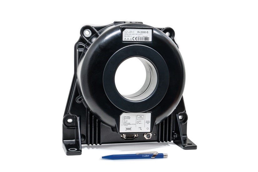
The complete transducer is shown in figure 8. The housing is metallic to give best shielding from external sources of interference. EMC immunity is further improved by situating the fluxgate inside the primary magnetic circuit.

Figure 8: The IN 2000 transducer
Table of key performance parameters.
The values of some important specification parameters of the IN 2000 are shown in Table 1.
| Parameter | Symbol | Unit | Maximum Value; -40 OC to 85 OC |
| Supply voltage | UC | Volts | +/- 15, +/- 5% |
| Nominal current measuring range | IPN | A rms | +/-2000 (IN 2000 transducer); AC and DC |
| Total current measuring range | IPM | A | +/- 3000 Amps |
| Number of secondary turns | Ncomp | 2000 | |
| Output RMS noise up to 10 Hz, 10 kHz, 160 kHz | Ino | ppm | 0.1, 4, 10 respectively |
| Output peak-to-peak ripple at 16 kHz | Ino pp | ppm | 50 |
| Offset at output | IOE | ppm | +/- 10 |
| Temperature coefficient of IOE | TCIOE | ppm/K | 0.1 |
| Linearity error over total measuring range | eL | ppm | < 3 |
| Step response time to 90% of IPN | tr | ms | < 1 |
| Frequency bandwidth (-3dB) | BW | kHz | 140 |
Table 1: Some performance parameters. All values expressed as ppm are relative to the total current measuring range.
Characterization results.
An extensive characterization of the IN 2000 has been performed over the full temperature range. As an example, figure 9 shows the accuracy of a population of parts both at -40 OC and at 85 OC.

Figure 9. Characterization of the IN 2000 thermal drift compared with 25 OC at cold and hot extremes of temperature.
Conclusion
In general the validation of apparatus and equipment is made by certified laboratories using high-performance test benches supported by high-technology measuring devices including extremely accurate current transducers. These must therefore maintain their accuracy over the full temperature range of the equipment tested, for example, in automotive tests benches.
Performance which is needed for test equipment is also desirable for traditional industrial applications which are more and more demanding in high-performance applications such as medical equipment (e.g. MRI, proton therapy etc.), precision motor controllers and metering.
The IN 2000 transducer represents a new step forward in the performance which may be obtained from fluxgate transducers. Its high accuracy and low noise, both maintained over a wide temperature range, together with its compact physical size, will increase the breadth of applications for which this type of current transducer is the optimum choice.