LEM new identity

Conheça mais sobre a LEM

Já são mais de 30 anos de parceria entre AMDS4 e LEM, nós como representantes e distribuidores oficiais da marca no Brasil e América do Sul, temos a LEM como nossa principal marca e símbolo de qualidade de nossos produtos.

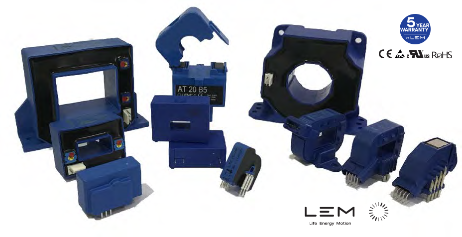
A LEM é o maior fabricante de transdutores de corrente e tensão do mundo. Além de alta qualidade e tecnologia, ela oferece uma grande variedade em produtos que suprem as diversas necessidades da indústria e dos setores técnicos ligados ao aprimoramento ou desenvolvimento de projetos tecnológicos.


Fonte: Linkedin LEM 

  • Além da já citada qualidade e tecnologia, outro grande e importante diferencial dos componentes LEM, são os 5 anos de garantia oferecidos em seus produtos.
  • Para se manter como a maior fabricante mundial de transdutores, a LEM investe constantemente no desenvolvimento e aprimoramento de seus produtos, ficando sempre na vanguarda da tecnologia quando o assunto é medição de corrente e de tensão.


  • A LEM também promove o desenvolvimento de novos produtos, para que se adequem e atendam as necessidades do cliente, quando necessário a produção em grande escala.
  • Se o projeto é desenvolvido sob sigilo industrial, a LEM oferece a assinatura de NDA (Non-Disclosure Agreement), que garante o sigilo e a segurança de informações técnicas e de desenvolvimento.

Catálogo geral LEM: https://www.amds4.com.br/bank/Current%20&%20Voltage%20Transducers%20for%20industrial%20application_0.pdf

IMG 01

Monitoramento remoto de energia IoT para Smart Grid

A IoT (Internet of Things) é perfeitamente adequada para o lançamento da rede inteligente, graças aos requisitos de longo alcance e ao pequeno tamanho de dados necessários para a transmissão. Usando RF de banda estreita, o padrão para comunicação de longo alcance, é agora possível uma solução inovadora de monitoramento remoto de energia.

A solução consiste em medidores de energia sem fio para o monitoramento remoto de equipamentos elétricos com hardware, conectividade M2M (LORA, SIGFOX, 3G / GPRS …) e serviços web para gerenciar os dados coletados (histórico, alertas, gráficos, estatísticas, etc.). Essa solução de IoT simplifica a implementação da rede e a instalação pelo usuário final, reduz os custos de infraestrutura (sem repetidores) e é geralmente compatível com as soluções existentes. Essa abordagem é ideal para IoT devido à pequena carga útil, aos requisitos de longo alcance e ao pequeno tamanho de dados necessários para a transmissão.

A configuração de rede em estrela da IoT é típica para implantação de smart grid.


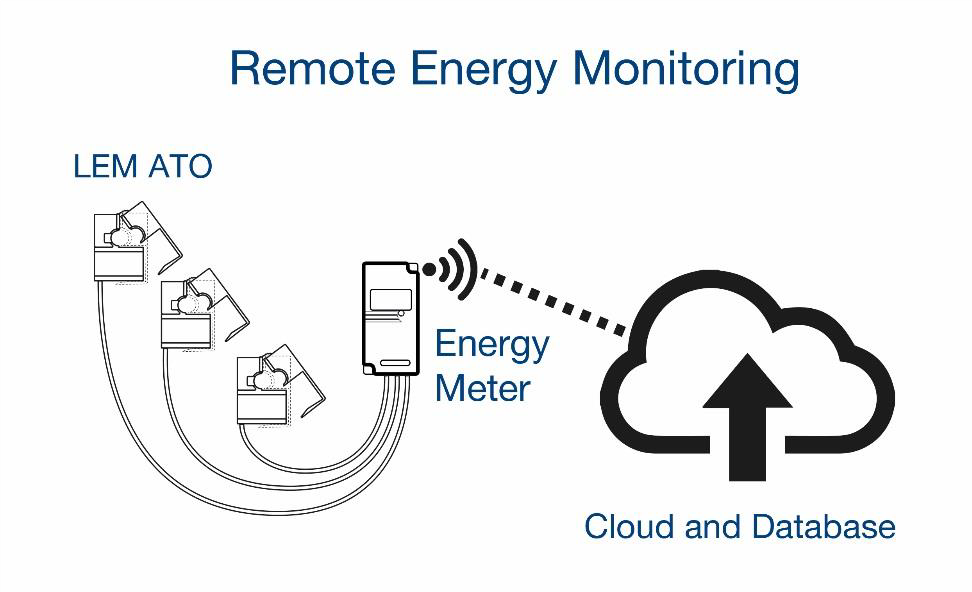
A aplicação típica para monitoramento de energia é identificar o equilíbrio do consumo de energia e a análise de consumo adicional para identificar as áreas a serem reparadas. Cada medidor de energia sem fio (1), usando LEM ATO (A) ou LEM ART (B), é conectado à Internet RF de longo alcance (2) e transmite (3) dados de manutenção para um servidor web seguro (4).

Os usuários finais podem acompanhar o uso do equipamento remotamente (ciclos, horário de trabalho, consumo etc.) ou receber alertas quando uma anomalia é detectada, como perda de energia ou picos de energia (5). Os dispositivos típicos que têm sua energia medida são itens com motores elétricos, ventiladores, bombas e compressores.

As vantagens dessa solução são a simplicidade de instalação do LEM ATO ou LEM ART, a conexão pela internet, as medições em tempo real e a autonomia do medidor de energia. O modo de operação é a aquisição de corrente de RMS de 1s a cada 10 segundos e envia estatísticas de consumo atuais a cada 10 ou 15 minutos.

As vantagens do monitoramento de energia remota baseado em IoT são:
• Não há necessidade de implantar uma infraestrutura de rede local
• Monitoramento de equipamentos internos e externos
• ampla cobertura de área
• Consumo de energia muito baixo, resultando em medidores de energia autônomos de longa duração
• Acessível e implantável com sensores LEM ATO ou LEM ART.

LEM ATO em conformidade com a norma IEC 61869-2.

Os transformadores de corrente de núcleo dividido não são novos, mas as tecnologias convencionais usadas nesses transformadores têm apresentado inúmeras deficiências – entre elas, soluções que utilizavam materiais caros ou que proporcionavam baixo desempenho. Nesse caso, a imprecisão não se refere às leituras em si, mas à linearidade, à sustentabilidade de uma leitura ao longo do tempo e à precisão da corrente em relação à tensão (deslocamento de fase). O novo padrão Smart Grid IEC 61869-2 requer tanto precisão quanto deslocamento de fase para estar dentro da Classe 1.

O transformador de corrente de núcleo dividido LEM “ATO” com Ferrite melhora drasticamente a permeabilidade magnética, permitindo que esses transformadores tenham alta precisão e excelente linearidade, mesmo em níveis de corrente muito baixos, em conformidade com a norma IEC 61869-2. A dureza do material sólido (considere Ferrite como uma cerâmica) permite uma usinagem muito fina, proporcionando ¨gap´s¨ de ar de até alguns mícrons que são estáveis ​​por muitos anos. Materiais laminados como FeSi ou FeNi não permitem espaços de ar menores que 20 ou 30 mícrons, e estes são mais sensíveis a mudanças de temperatura e envelhecimento. Some aos pequenos ¨Gap´s¨ de ar, à melhor linearidade da ferrita a baixa excitação magnética (ou seja, para baixa corrente), e a ferrita oferece um desempenho melhor do que FeNi-80%, e a um custo menor.


Name LEM ATO LEM ART
Type Split-Core Current Transformer Flexible Rogowski Coil
Range 10-125A 10-10000A
Material Ferrite Winding (no magnetic core)
IEC class Class 1 and 3 Class 0.5
Output Inst Ma (1:1000), 225-333mV 22.5mV/kA
Diameter 10-16mm 35, 70, 125, 175, 200, 300 mm
IP class IP 30 IP 57


Conclusão

O monitoramento remoto de energia baseado em IoT tem um período médio de amortização inferior a um ano. Os operadores de manutenção gastam 30% do seu tempo de trabalho na estrada e qualquer necessidade de reparo normalmente é de duas a três viagens, portanto, essa solução LEM economiza tempo. Alguns locais ou equipamentos da planta são de difícil acesso (desperdício de tempo e risco para o operador) e não há como adicionar transformadores de núcleo sólido sem um encerramento dispendioso do sistema. O transformador de corrente sem fio LEM de núcleo aberto e sem contato LEM pode ser simplesmente encaixado em um cabo, sem a necessidade de parafusar ou soldar suportes complexos, simplificando a instalação e a manutenção.Conclusão

A configuração da IoT combinada com a IEC Smart Grid, o ATO da LEM permite a readequação imediata de sistemas de monitoramento remoto de alto desempenho e de baixo custo, medição de energia e supervisão de instalações.

Sobre o LEM

A LEM é líder de mercado no fornecimento de soluções inovadoras e de alta qualidade para medir parâmetros elétricos para uma ampla gama de aplicações. O LEM responde à demanda por um sensor de energia preciso, confiável e fácil de instalar para futuras Smart Cities.

IMG-01-amds4

Why is LEM’s Rogowski Coil better than a Transformer?


Distribution Overhead Line Monitoring with LEM’s ART Rogowski coil

New line current sensors allow utilities to monitor their overhead distribution lines to maximize their capacity and prevent clearance violations thus improving reliability and efficiency of the MV Distribution Grid.

The High Voltage transmission grid is already highly automated and monitored through SCADA and Energy Management Systems. In contrast, the Medium-Low Voltage distribution grid has very limited monitoring and control. Why? – More often than not, Utilities fail to monitor their many medium voltage substations, this is due to the expense of retrofitting with today’s solutions and of the time it takes to plan and build. The implementation of traditional substation monitoring requires complicated engineering, this includes the use of remote terminal units with new conduits, wiring to relays and current transformers. Engineers must schedule outages to disconnect the feeders, which takes time and may only be possible during low power consumption needs. Once the hardware has been installed, the utility has to program and integrate all the hardware into a complex SCADA system, which is a significant and difficult challenge for many utilities. There must be a better way.

Below the feeder level, remote monitoring is absent with the exception of customer billing meter points where smart meters are becoming prevalent to read, monitor and control. However, these smart meters are only collecting and communicating Voltage, Current , Power, Reactive Power, S, Energy  data rather than power quality data sets like Cos (Phi), Total Harmonic Distortion, flicker, voltage dips, transients, waveforms, time series etc. The smart meter does not collect a lot of data outside of its billing focused function. Substations and distribution power lines are two of the most valuable assets for utilities that require crucial power flow data to provide the most reliable service.

The most relevant data in the distribution grid is about the location and cause of faults and non-fault events, high-impedance faults, consumption peaks, handling distributed renewable energy and EV charging, feeder outages, and many others – all high-value data that is not addressed by today’s systems.

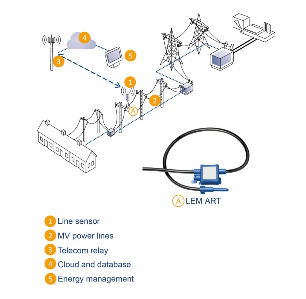
Now monitoring overhead power lines has been made possible faster, easier and cheaper with new Internet of Things telecom networks like NB-IoT and LPWAN.Thanks to a line sensor (1), installed between two MV poles (2), the grid operator can visualize, in real-time, the current flow in order to optimize the power line capacity to distribute more electricity. The wireless line sensor (1) sends data over a telecom relay (3) to a secured database in the cloud (4) or on premise. The energy management platform (5) can regulate, alert and notify the maintenance team if needed. New line sensors are now using the LEM Rogowski coil ART (A) to measure the current, detect line aging depending on the level of current, and prioritize line capacity.


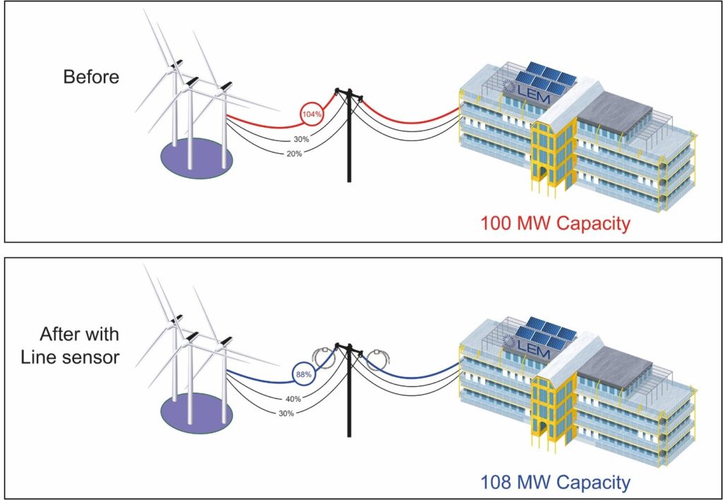
Before without visibility about the grid, the generated renewable energy distributed through an overhead line could be overloaded (red). Thanks to the three-phase line sensor system, the extra power in one of the line can be re-distributed to the adjacent lines (black) therefore reducing the initial line (blue) capacity to an acceptable level. Overall, the capacity output of the power grid is then maximized (fig. 1).


Figure 1: Before and after line sensor installation


In addition, the line sensor (1-35kV distribution grid) provides periodic time synchronized measurements to facilitate improved situational awareness and operations: current, both amplitude and phase, conductor surface temperature and detects fault conditions enabling rapid identification and notification. This three phase line sensor system in the power distribution are equalized in real-time among the different lines within a meshed network

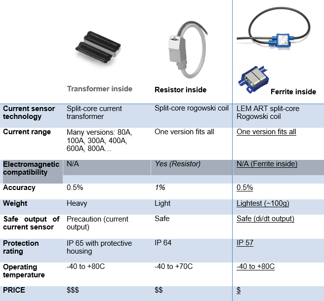
The AC measurement can now be achieved with the LEM ART split-core rogowski coil, see below table for the summary of the ART advantages compared to two other current measurement techniques used in the Line sensor.


ART is the clear winner of this comparison with a practical one size fits all current loop,  excellent ferrite core, great accuracy, light, safe mV output and water resistant coil.

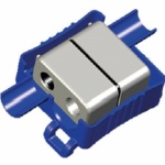
ART Ferrite core

Recent developments have revolutionized the characteristics of ferrite at 50/60Hz, bringing many advantages. This new type of ferrite has significantly improved permeability and has been implemented in this ART Rogowski coil (fig. 2). ART takes advantage of the intrinsic ferrite qualities:

  • High accuracy and excellent linearity, even at very low current levels
  • No phase-shift between input and output currents
  • No air gaps and virtually insensitive to ageing and temperature changes
  • Low position dependent error close to the clasp of the coil (see ART Sensitivity)
  • Low cost versus potentiometer based Rogowski coils


Fig. 2. Ferrite core of LEM ART Rogowski coils


ART Sensitivity

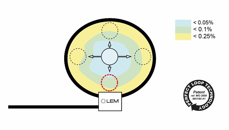
The overall sensitivity to the position of the primary conductor can be controlled, but usually close to the clasp errors are often unavoidable, except for the patented ferrite based ART Rogowski coil (fig. 3).


Fig. 3. Position sensitivity of ART Rogowski coil


Conclusion

The new ART rogowski coil class 0.5 has made huge progress, allowing small, light, sensitive and flexible current sensing for MV grids. The major improvements that have been made in the design and manufacturing processes have enabled a reduction in both the cost and the sensitivity to the coil positioning around the primary cable.

People consume more electricity than ever before and have an expectation that they will access their electricity without fault or interruption. The line sensor provides situational awareness along distribution feeders allowing utilities to operate and respond based on prevailing conditions. The system directs preemptive patrol and maintenance crews to the affected grid locations, enabling utilities to avoid potential short or long electricity interruptions. It reduces outage frequency, resulting in the reduction of the momentary average interruption frequency index (MAIFI) and system average interruption frequency index (SAIFI). Both indexes serve as valuable tools for evaluating a utility’s performance and reliability because some countries have already put in place regulations that require a utility to reimburse customers for long electricity interruptions.

When installed with the hot stick or insulated gloves on the overhead power line, LEM ART rogowski is a safe, easy-to-install, light but robust current measurement alternative to heavy and expensive current transformers, therefore improving the overall performance, reliability and efficiency of the line sensor.

About the author

Patrick Schuler, LEM

Patrick Schuler has been working in the internet, telecommunications, smart grid, power electronics and power utility sector for more than 15 years. Since joining LEM in September 2014, Patrick has been responsible for defining the global smart grid offering and managing smart grid business development. As a smart grid expert, Patrick is a member of the IEC’s world smart city community in Geneva and was the former smart grid chairman at the China European Chamber of Commerce in Beijing.

About LEM

LEM is the market leader in providing innovative and high quality solutions for measuring electrical parameters for a broad range of applications in drives and welding, renewable energies and power supplies, traction, high precision, conventional and green cars businesses. LEM has production plants in Beijing (China), Geneva (Switzerland), Sofia (Bulgaria) and Tokyo (Japan). With regional sales offices near its customers’ locations, the company is able to offer a seamless service around the globe. LEM is a mid-size, global company with approximately 1’450 employees worldwide and reported sales of CHF 264.5 million in financial year 2016/17. LEM City answers the demand for an accurate, reliable and easy-to-install energy sensor for future Smart Cities.

LEM City – at the heart of our planet‘s energy measurements.

www.lemcity.com

IMG-10

Why do current transducers go digital?

LEM pioneers current sensing and develops digital output transducers with a sigma-delta bit stream interface (Subtitle)

By: Pascal Maeder (Global Product Manager, Drives/Welding)

Sources: David Jobling (ASIC Development Group Manager)
Stéphane Rollier (Product & Marcom Manager)
Mathieu Béguin (Marketing Engineer)


Why do current transducers go digital?

A couple of years ago, LEM’s Sales & Marketing observed the first signs of a technological turnaround: some of the leading OEMs (Original Equipment Manufacturers) in the servo-drives and robot industry were thinking of abandoning analog interfaces on their systems.

This change was driven by the evolution of controllers: the “brains of the machines”. The controllers function fully digitally internally and generally only had A/D’s (analog-to-digital converters) on their interfaces. This is no longer the case today; the A/D’s are disappearing in new controllers and customers are now asking for current transducers with a digital output so that they can easily connect to their new micro-controllers. Another advantage of a digital interface is that it is less sensitive to electro-magnetic interference.

Defining and developing products based on a new technology is complex and long: you cannot afford to get it wrong. After a comprehensive market survey conducted in 2013 by LEM’s marketing & product management teams, the R&D department started developing a Hall-based open-loop ASIC. The analog to digital (A/D) conversion is performed by an on-board sigma-delta modulator, giving a 1-bit serial bit stream output, with a sigma-delta modulator at the output.

The first prototype transducers were delivered to “alpha customers” at the end of 2015. The initial feedback was positive and LEM presented these future products at the PCIM tradeshow 2016 in Nuremberg, where more users showed interest in using this new technology.


The products

LEM proposed a range of digital output versions of the successful HO and HLSR open-loop Hall effect current transducers. These new components are for nominal current measurements of 10, 32, 50, 80, 100, 120, 150, 200, 250 ARMS in 3 different mechanical designs (PCB and panel mounting) and provide up to 12 bit resolution with 20 kHz bandwidth. The single-bit output minimizes the connections required, enabling highly compact transducers, and the digital output allows the user to choose the filter used on the bitstream to optimize between resolution and response time, according to the application. Digital outputs are also intrinsically immune to noise in hostile environments.


Fig.1: HLSR 50-PW, the digital version of LEM’s successful HLSR 50-P transducer (analog output).


The digital interface

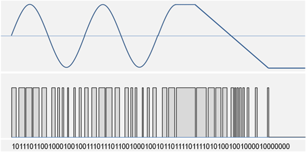
The transducer output is a bit stream where the density of 1’s depends on the current measured, as illustrated in figure 2.


Fig.2: The digital conversion with a ∑Δ Modulator.


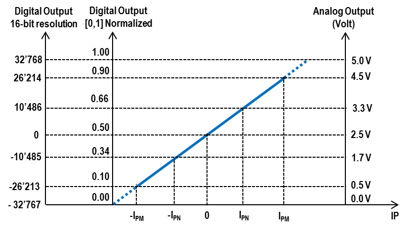
The detail of the transfer function is shown in figure 3. This shows the average density of 1’s on a scale from 0 to 1, and the same output if it is filtered and represented as a 16-bit word on a scale from 0 to 65’535 (decimal). See the next section for more on filtering options. Figure 3 also shows the equivalent output from an analog sensor. As with the analog sensor the performance of the new sensor is over the range +/-IPM, corresponding to an average density of 1’s from 0.1 to 0.9.


Figure 3: Transfer function.


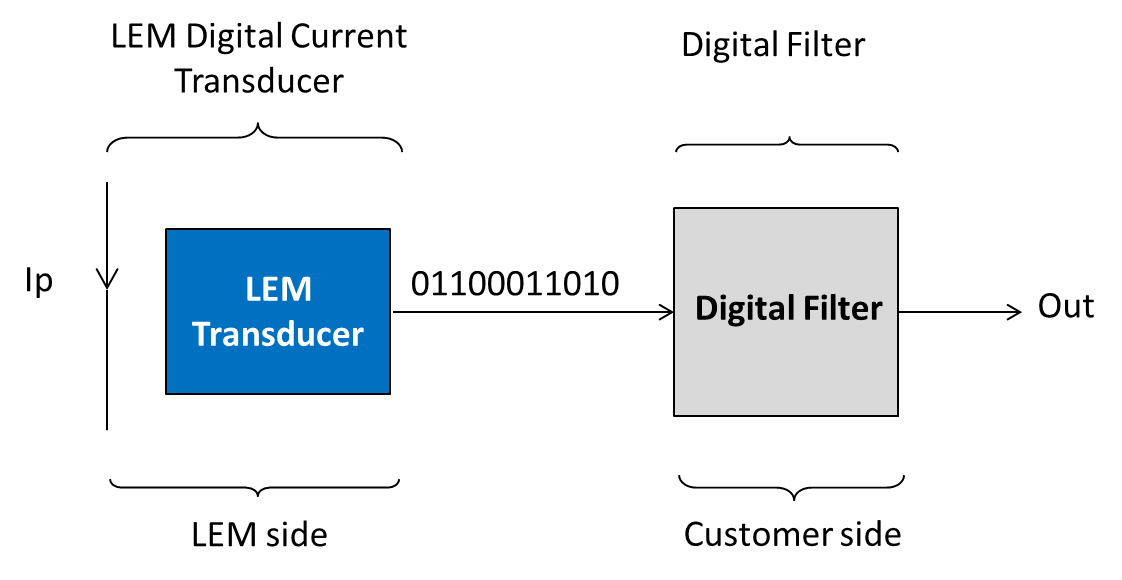
The digital filter is implemented by the user, see figure 4. The advantage is that the number of connections to the transducer is minimized; each user can decide the filter(s) best suited to the application and the output format can be selected to match the system requirements.


Figure 4: LEM provides a bit stream output.


Performances and filter choices

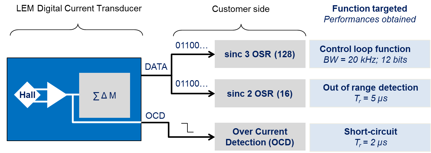
Any conversion from an analog to a digital signal involves quantization, and the error between the digital signal and the exact value of the analog signal it represents is equivalent to the addition of noise. The output from a sigma-delta modulator is more than simply a bitstream with a certain density of 1’s and 0’s; the sequence is randomized in a way that pushes the quantization noise out of band to frequencies higher than those of interest for current measurement. The user processes the bitstream in a digital filter which rejects the high frequency noise. As with any filter, compromises are made to optimize system performance: a narrow bandwidth gives lowest noise (or highest resolution) at the expense of response time, and vice versa. In the example of figure 5 the bitstream is processed twice: in a 20 kHz filter which gives a resolution of 12 bits for accurate measurement of the primary current and in a wideband filter to detect excess currents with a response time of 5μs. Additionally the transducer internal OCD (over current detect) output allows detection of short circuits with a response time of only 2.7 µs.


Figure 5: Application example with OSR and filter order influence on response time and resolution.


Bits are processed one at a time in the digital filter. Due to the modulator oversampling ratio (OSR), the digital filter output can be processed every OSR bits with no loss of information within the band of interest.

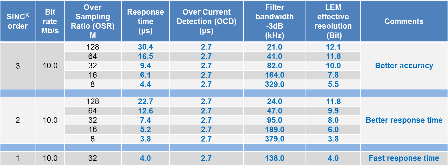
The latency of filter depends on its very nature: output is delayed by 2 x OSR x CLK period for a sinc2 whereas 3 x OSR x CLK period are needed to get the exact output after a step response with the very common sinc3 filter. The bit rate at the output of LEM’s new sensors is 10 Mb/s. The combination of OSR, filter choice and bit rate leads to the response time, the bandwidth and the effective resolution of each of the signal paths connected to the bitstream, as shown in figure 6 of the HO 150-NPW performance.


Figure 6: HO 150-NPW performances: Performances = f (OSR, SINC K FILTER, BANDWIDTH).


The resolution of the complete system including the analog part of the transducer, the sigma-delta modulator and the digital filter is limited either by the quantization noise inherent to the system or by the analog noise from the Hall cells and amplifiers. For fast response times (for example with an OSR of 16 and a sinc2 filter) the resolution is defined by the system and will be the same with any transducer. If the filter is changed to sinc3 and the OSR is increased the effective resolution is improved but will be limited to 11 – 13 bits (depending on the sensor sensitivity) by analog noise. The term “Effective” resolution is used because for system convenience the filter may output a word with a length of 16 bits or 2 x 8 bits. However only the most significant bits corresponding to the effective resolution contain useful information, the less significant bits contain noise.

Usually the digital filter output is sampled at a frequency equal to the bit rate divided by the OSR; this is referred to as decimation. With the LEM sensors if the OSR is 64 the output is updated every 6.4 us.


Physical interfaces

To transmit the bitstream LEM offers the choice between two physical interfaces. In both cases the bit rate is 10 Mb/s.


CMOS Single-ended

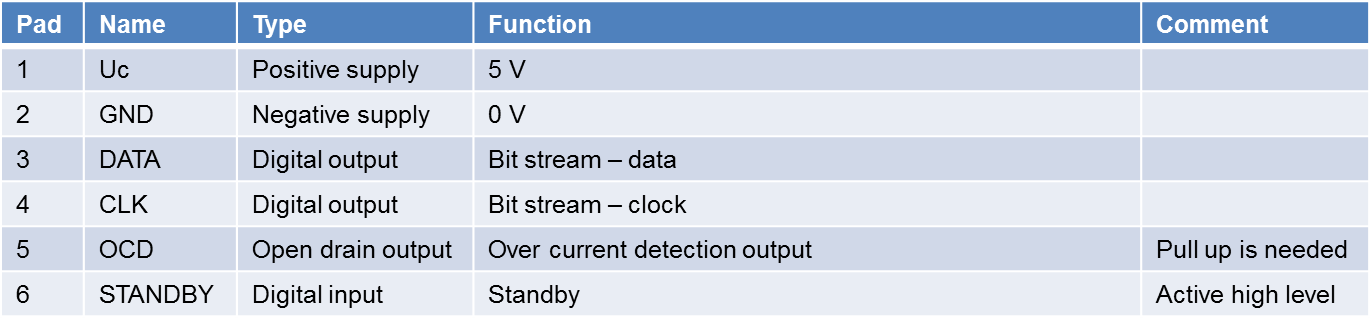
With the first, clock and data are provided as single-ended CMOS levels (Uc and GND). This is suitable for transmission over short distances, up to some 10’s of centimeters, after which EMC issues may become important. The maximum allowed capacitive load is 30 pF. The transducer pin allocation and timing diagram are shown in figures 7-8.


Figure 7: Single-Ended CMOS levels wiring.


Figure 8: Single-ended output (CMOS levels).


Manchester RS422

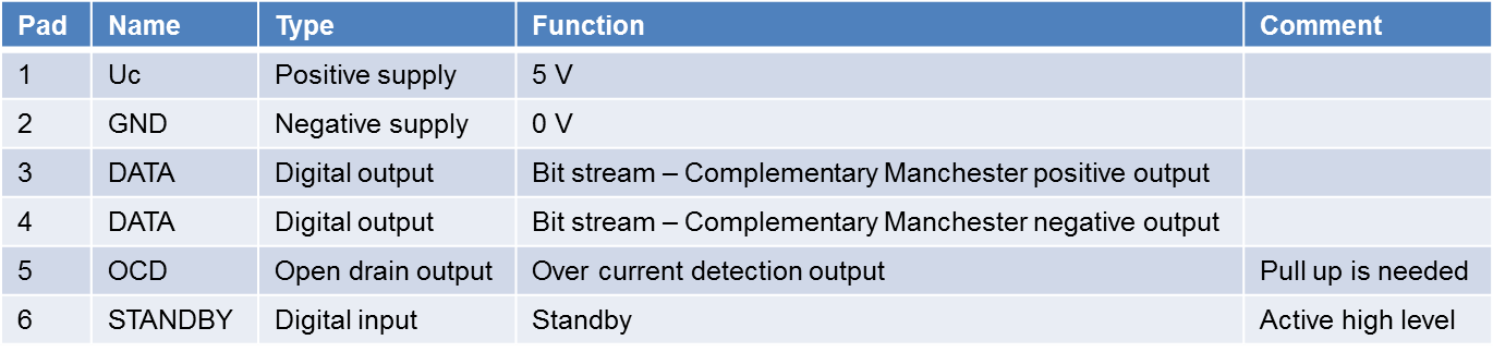
The second interface is suitable for transmission over longer distances. In this case the clock and data are combined as a Manchester coded signal. This is output on transducer pin 3 and its complement on pin 4. The differential signal thus generated is compatible with the RS422 standard. By keeping the two signal tracks physically close, EMC effects, both transmitted and received, can be kept to a low level. The pin allocation and timing diagrams are shown in figures 9-10.


Figure 9: Manchester interfaces wiring.


Figure 10: Manchester transmissions data.


Conclusion

This technological leap is not “just a new family of transducers” for LEM and the industry.

The outlook for digital output transducers is very encouraging: customer feedback shows that a significant part of the market will shift to digital interfaces, starting with the high-end servo drives. We expect more industry segments to follow this trend. Our industry is going digital and LEM is leading the way!

Figure 4: LPSR current transducer with an ASIC using the Hall effect Closed Loop technology

MAKING SINGLE-PHASE SOLAR INVERTERS SMALLER, CHEAPER & SAFER

ABSTRACT :


New technologies allow photo-voltaic (PV) inverters to switch at ever higher frequencies and consequently they are becoming much smaller and lighter. International competition and the move away from subsidies for new installations mean that there is strong pressure on their cost. The current transducers used in PV inverters must follow these trends: they must have a reduced footprint while having equivalent or improved performance at lower cost, compared to the transducers they replace. Typically PV installations use current transducers in three places. One is on the DC side, for the maximum power point tracking (MPPT) system. Two are on the AC side: first to define the parameters of the output current waveform, and secondly for safety reasons: for Residual Current Measurement (RCM) in the output caused by earth leakages, so the system may be closed down if necessary. This article shows how recently introduced LEM transducers can be used for MPPT and for AC waveform management, and then presents a new compact transducer specifically designed for RCM.


  1. INTRODUCTION


Figure 1 shows main components around an inverter in a PV system typically used in residential installations of up to approximately 20kW. Several such inverters may be combined to make the complete installation which is connected to the grid via metering apparatus.

Figure 1. An inverter system for Photo-Voltaic installations.


Figure 2. Voltages and residual currents in the PV installation


During the last decade new silicon MOSFETs have been introduced in inverters, and in future MOSFETs based on SiC and GaN will begin to replace those using silicon. This is allowing higher frequency switching which in turn means that reactive components (inductors, capacitors) of lower value, and hence smaller physical dimensions, can be used. A 2kW inverter available in 2010 and weighing over 20 kg according to the manufacturer’s datasheet has been replaced in 2016 by a model weighing less than 10 kg. In order that the current transducers used as measurement devices in a PV system continue to use a negligible part of the overall space and weight budget, their size must also reduce without any performance degradation. Similarly their cost must reduce to follow the downwards cost trend of the complete inverter system.


There are 3 LEM current transducers in figure 1, all containing custom proprietary CMOS ASICs with fully integrated Hall cells. On the DC side of the inverter there is an open-loop GO; on the AC side a closed loop LPSR for the inverter control system and at the output an LDSR, a new differential transducer for RCM also with a closed loop architecture. (For a detailed explanation of Hall effect open and closed loop transducers see Reference (1)


Figure 2 shows the voltage waveforms on the DC and AC sides of the inverter. Note that in a transformer-less system, the “DC side” does indeed have a DC voltage corresponding to the output of the photovoltaic cells between the PV+ and PV- nodes (this may be increased by a DC-DC converter) but each of the PV nodes also has an AC voltage whose peak value is similar to the peak output voltage of the AC side. If not considered at the system level this represents a serious safety hazard.


  1. CURRENT TRANSDUCERS IN THE PV INVERTER


2.1 The DC side.


Depending on the illumination intensity of the PV cells the load which maximizes the power transferred from them varies, and so the control system uses a real-time MPPT algorithm to load the cells for maximum power transfer. In the case of motorized PV panels the MPPT algorithm can also be used to obtain the optimum orientation. Since the target of the algorithm is simply to find the peak in the power transfer the accuracy requirement on the current transducer used is not demanding, and an open-loop transducer is ideal for this purpose. LEM has recently introduced the GO family of transducers (Reference (2)) which have the primary conductor integrated into a standard IC package. This gives a 70% PCB footprint reduction compared with a small transducer including a magnetic circuit. The SOIC-16 transducer is shown in figure 3. The principal specification parameters of the GO-SMS transducer in its SOIC-16 packaging are shown in Table 1.

Figure 3: GO-SMS transducer in an SOIC-16 package


Parameter GO-SMS transducers
Nominal current range (A) 10  – 30
External field immunity Yes: gradient sensor
Insulation test, 50 Hz, 1 min (kV) 3
Impulse test voltage, 50 us (kV) 4
Creepage, clearance distances (mm) 7.5
Accuracy over 25 – 105°C (%) 3.25
Primary resistance (mW)  0.75
Out-of-range detection Yes, 10 ms response time
Short-circuit detection Yes, 2.1 ms response time
Response time ms <2
Offset drift (10 A model) (mA/K) 0.94
Sensitivity drift (ppm/K) 150
Magnetic offset 0
Footprint (mm2) 100


Table 1. Main performances of the GO-SMS transducer


The accuracy of the GO transducers exceeds that which is needed for the MPPT algorithm, and they may also be used at system level for other purposes, for example by comparing the outputs of different PV panels receiving similar illumination to identify faulty panels.


2.2 The AC side.


The transducer shown after the inverter in figure 1 is a key element of the control loop which drives the inverter switches and so governs the accuracy of the current output waveform. It must have a fast response time, low noise and good linearity, and in particular the offset and its drift with temperature must be low so that the DC component of the current injected into the grid meets regulatory requirements. Closed-loop transducers have an architecture which, due to the transformer effect, give good speed, noise and linearity performance. Historically the low offset requirements have been met using a fluxgate as the magnetically sensitive element. However low offset (and low offset drift) are now achieved by design innovations in the CMOS ASIC used in, for example, the LPSR family of transducers. The ASIC includes Hall cells and low offset amplifiers merged in a new patented architecture which allows the input related offset drift of the sensor to be around 4ppm/°C (25 A model). The result is a sensor whose construction is simpler than that of the fluxgate families with similar performance. Table 2 summarizes the key performance parameters. The LPSR family of transducers has been described in detail in Reference (3).

Figure 4: LPSR current transducer with an ASIC using the Hall effect Closed Loop technology


Parameter LPSR 25-NP
Sensitivity error (%) +/-0.2
Temperature coefficient of sensitivity (ppm/°C) +/- 40
Electrical offset voltage (mV) +/- 1
Magnetic offset current (mA) after overload 10 x IPN (Referred to primary) +/- 60
Reference Voltage VREF @ IP = 0 2.485 – 2.515
Temperature coefficient of VREF @ IP = 0 (ppm/°C of 2.5 V) +/- 70
Temperature coefficient of VOUT @ IP = 0 (ppm/°C of 2.5 V) +/- 4
Linearity (%) +/- 0.1
Response time @ 90 % of IPN step (ns) 400
Overall accuracy (% of IPN) @ 25°C 0.8
Overall accuracy @ TA=85°C (% of IPN) 0.85
Overall accuracy @ TA=105°C (% of IPN) 0.9


Table 2. Main performances of LPSR 25-NP


2.3 Residual Current Measurement for Safety.


The nodes PV+ and PV- of figure 1 are physically large in a typical PV system. The average voltage on each node, relative to ground, is half of the voltage from the PV cells but on this is added an AC voltage whose peak-peak value is similar to that of the cells. In the event of a person touching the PV+ or PV- nodes (or, in general, any node on the DC side of the inverter) a leakage current will flow out of the system through the person to ground. Since there is only one node in the system whose potential is maintained at ground level, the N node at the output, this leakage must flow back into the system through the N node, and this will cause a DC current imbalance, or residual current, between the L and N outputs. This residual current must be detected, permitting the system to take very fast action to protect the person who has caused the residual current to flow. Among the challenges in RCM are:

  1. The absolute value of the current to be detected is low, some 10’s of mA, and so the transducer offsets must be low enough for this level of current to be detected;
  2. The AC current at the output is between zero and 10’s of A, and the residual current must be detected in the presence of this;
  • Capacitance between the PV panels and ground mean that there is always some current flowing to ground, and the system objective is to distinguish these from an extra current caused by dangerous human contact.

Figure 2 shows the leakage current path in a simplified inverter system with the new LEM LDSR transducer used for RCM.


Of the three challenges listed, (i) and (ii) have been achieved in the LDSR by a special transducer design dedicated to RCM, while (iii) is achieved by applying a signal processing algorithm to the transducer output.


Figure 5 shows the principal of RCM: a Hall cell ASIC similar to that used in the LPSR example presented above is the heart of a closed-loop transducer. The AC currents I1 and I2 cancel, and the low residual current is detected by the Hall cell ASIC and compensated by a secondary winding having far fewer turns than in the case of the LPSR, since the current to be detected is much lower.

Figure 5: RCM operation principle based on the Hall effect closed loop technology.


Detailed analyses of the effect of the position of the primary conductors in figure 5 shows that the cancellation of I1 and I2 is not perfect and the residual magnetic field in the air gap depends on their position. Therefore it was decided to define the primary positions exactly by placing them on a multi-layer PCB inside the transducer. Furthermore, for RCM only a few dozen turns are required for the secondary coil, which means they can also be written on a PCB. In this way an innovative sensor has been designed whose construction is far simpler than that of earlier sensors. Having the primary conductors on a PCB limits the maximum primary current, but the allowed value of 35 A in each conductor is more than enough for domestic installations.


With primary currents of this value the design of the PCB on which the LDSR is mounted is important. Simulations have shown that with an optimized design the temperature rise in the transducer due to a 35 A primary current is limited to 13 oC

Figure 6. The LDSR transducer with planar primary conductors and magnetic core.


Figure 6 shows a simplified drawing of the LDSR transducer with its package removed. For test purposes an additional coil is wound on the ASIC PCB concentrically with the secondary circuit. This is useful for a system test: a current passed through it will give a transducer output in the same way as the current difference between the primaries.


Figure 6 shows a transducer with a single primary phase, it is also available with three phases.


As with the LPSR transducer the ASIC is designed for minimum offset, and the offset referred back to the input current is reduced by placing a hole in the PCB under the ASIC, allowing the smallest possible air gap in the magnetic circuit.


Because of the high sensitivity of the LDSR a magnetic shield (not shown in figure 6, for clarity) is placed around the ASIC and air gap.


Figure 7 shows a photograph of the LDSR transducer.

Figure 7. LDSR in single and three phase versions.


Parameter LDSR 0.3-TP
Sensitivity error (%) +/-2
Temperature coefficient of sensitivity (ppm/°C) +/- 250
Accuracy (mA) without initial offset @ from -40 to +105°C +/-40
Accuracy (mA) without initial offset @ 30 mA for +/-30 mA instantaneous DC jump +/- 8
Accuracy (mA) without initial offset @ 60 mA for +/-60 mA instantaneous DC jump +/- 12
Accuracy (mA) without initial offset @ 150 mA for +/-150 mA instantaneous DC jump +/- 20
Reference Voltage VREF @ IPRN = 0 2.485 – 2.515
Response time @ 90 % of IPRN step (us) 300

Table 3. Main performances of LDSR 0.3-TP


In general the leakage currents detected by the LDSR will have an AC and a DC component and each user will use a specific algorithm on the transducer output to determine when a leakage is ‘excessive’ and take appropriate action. A particularly challenging case occurs when there is a large natural and variable AC leakage component (depending on ambient humidity, for example) through parasitic capacitances and the extra leakage caused by a person touching the DC side must be detected. The impedance presented by a person is largely resistive, and so, as shown in Figure 8, the extra current flowing makes almost no difference to the RMS value of the leakage current; the main effect is a change of phase.

Figure 8: The effect of adding a resistive path to the leakage.


In general of course there is also noise which adds to the real and imaginary currents of figure 8. In a case where only one known frequency must be analysed in a sampled waveform the Goertzel algorithm is particularly efficient. In figure 9 a 30mA rms ‘person leakage’ current is added to a 300mA rms ‘capacitive leakage’ current with 7.5mArms of noise at time = 0.1 s. The visible effect on the total leakage current is quite invisible, but after treatment with the Goertzel algorithm the 30mA current step is easily recovered and if this value exceeds a predefined threshold value appropriate action can be taken at the system level.

Figure 9. Simulation of residual current during fault and output of the Goertzel algorithm.


Conclusion.


This paper has used the example of photovoltaic installations to show the advances in recent LEM current transducers. Their size and cost are reducing while performance is maintained or improved. Transducers are now designed without the magnetic circuit or fluxgate component previously needed. This innovation is enabled by moving the complexity of transducer design into the custom Hall effect ASICs they use.


Reference (1): https://www.lem.com/en/file/3139/download

Reference (2): Bodo’s Power Systems April 2017 issue “A New Family of Miniature, Fast and Accurate Transducers for Isolated Current Measurement”

Reference (3): Bodo’s Power Systems May 2017 issue “Closed Loop Current Transducers with Excellent Performance are also Cost-Effective”

620-698-lem

Smart Transformer condition monitoring with Smart Meter and Rogowski Coils

Smart Grid for the City

The intelligent electricity network (smart grid) is the backbone of every smart city, since it:

Informs “prosumers” (proactive consumers or producers of energy) about their energy usage and enables them to make decisions about how, when to use, store or even resell electricity, as with solar panels on roof tops. This promotes the participation of residential, commercial and industrial buildings in energy conservation, efficiency and demand response programs.

Provides reliable integration of distributed renewable energies, energy storage and electric vehicle charging stations. This means smarter protection equipment and smarter substations to enable faster management of fault detection, isolation and restoration.

Improves the grid with smarter components (sensors, intelligent electronic devices, smart meters and so on) allowing control, automation, remote monitoring and real-time data sharing. By working together, these components provide the control center with information on current and future performance of the grid and a detailed status of critical components such as a transformer.

Smart Transformer = Smart Meter + Rogowski Coil

A leading metering provider has introduced the use of flexible LEM Rogowski coil sensors (ART) with a smart meter connected to the low-voltage (LV) side of a distribution transformer in an MV/LV substation. The software in the smart meter calculates the thermal and electrical models of the transformer based on the LV measurements information, providing its oil temperature and ageing rate as well as MV current values and energy flows. It is an innovative, more economical way to manage the distribution grid without having additional sensors on the MV side. The smart meter’s overall accuracy with the LEM ART is better than 1%, superior to conventional Class 0,5 meters associated with Class 0,5 current transformers (CTs).


Figure 1: MV/LV Substation


Within the MV/LV substation, the incoming power flow from the MV side (1) is managed by the MV switchgear (2) before being converted by the transformer (3) into LV (6). The smart meter (5) installed in the LV panel (4) measures the transformer’s (3) health with three independent current sensors – LEM ART (A). The ART allows safe commissioning of the smart meter on an existing live transformer.


Benefits for distribution system operators include:

  • Real-time thermal behavior, ageing rate, active and reactive losses of each distribution transformer.
  • LV load curves of consumers, producers and transformers allowing detection of non-technical losses.

Aggregation of active energy distributed by each MV-LV transformer allowing detection of non-technical issues on the MV side of the grid.

LEM Rogowski Coil (ART)


LEM has developed the ART current Rogowski sensor with the capability to measure up

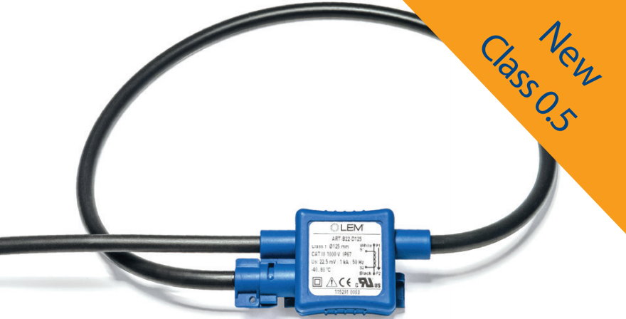
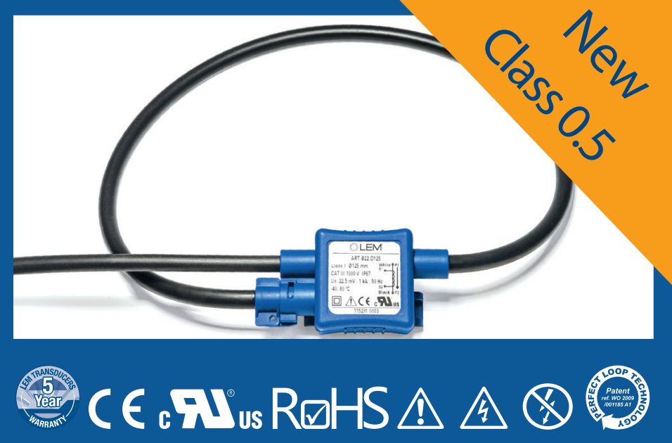
to 10,000A and beyond. The ART is a raw coil achieving IEC 61869 Class 0.5 accuracy without the need for additional components such as resistors or potentiometers, which have a risk of drift over time.

In addition, the ART labelled “Perfect Loop” has a unique patented coil clasp curing the inaccuracy caused by the sensitivity to the position of the conductor inside the loop. Finally, the ART provides the same ease of installation as split-core current transformers and a better Class 0.5 accuracy. The ART also has the best performance among other Rogowski coil players.


Figure 2: LEM ART features and performances versus competition


What is a Rogowski coil?

A Rogowski Coil is used to make an open-ended and flexible sensor that easily wraps around the conductor to be measured. It consists of a helical coil of wire with the lead from one end returning through the center of the coil to the other end, so that both terminals are at the same end of the coil. The coil length is selected according to the relevant primary cable diameter to provide optimal transfer characteristics.

This technology provides a very precise detection of the rate of change (derivative) of the primary current that induces a proportionate voltage at the terminals of the coil. This is then a current measuring technology only for AC currents. An electronic integrator circuit is usually added to convert that voltage signal into an output signal that is proportional to the primary current. In other words, the Rogowski Coil enables the manufacturing of very accurate and linear current sensors, at the price of additional electronics and calibration.

A  Rogowski coil has a lower inductance than current transformers, and consequently a better frequency response because it uses a non-magnetic core material. It is also highly linear, even with high primary currents, because it has no iron core that may saturate. This kind of sensor is thus particularly well adapted to power measurement systems that can be subjected to high or fast-changing currents. For measuring high currents, it has the additional advantages of small size and easy installation, while traditional current transformers are big and heavy.


Figure 2: Rogowski Coil principle


VOUT = – M*dIP/dt.

M is the mutual inductance between the primary conductor and the coil, which to some extent represents the coupling between the primary and secondary circuits.

The performance of such current sensors highly depends on the manufacturing quality of the Rogowski Coil, since equally spaced windings are required to provide high immunity to electromagnetic interference; the density of the turns must be uniform otherwise the coefficient M could change versus the position of the primary into the aperture.


Another critical characteristic is the closing point that induces a discontinuity in the coil, creating some sensitivity to external conductors as well as to the position of the measured conductor within the loop. The locking or clamping system should ensure a very precise and reproducible position of the coil extremities, as well as a high symmetry while having one of the extremities connected to the output cable. Some new technologies have recently appeared in this area, with special mechanical and electrical characteristics that allows much better accuracy and immunity to the primary cable positioning. While the error due to primary cable position was typically not better than +/-3% in the 50/60Hz frequency domain, it has been reduced to less than +/- 0.5% on some of the latest Rogowski Coil sensors.


Figure 4: ART Rogowski Coil current sensor from LEM


How LEM managed the challenge:

Two main technics are on the market to make Rogowski coils accurate:

  • The first is to buy standard wound wire on the market and to make the loop connected to a resistor, which will be used for the accuracy calibration.
  • The second is a so-called “pure Rogowski coil” consisting in winding very accurately a regular copper wire all along its length to ensure the final accuracy of the sensor.

While the first is really easy to produce at a low cost, this is nevertheless highly sensitive to external environments, less accurate, and less reliable as it brings in more components.

At the opposite end, the Pure Rogowski coil requires much more investments and knowledge on manufacturing process.

The really thin LEM ART Rogowski coil is part of this second method and has a gain of 22.5 mV/kA; it includes an electrostatic shield to protect against external fields (LEM patent), optimizing performance for small current measurements.

The locking system has also been a key point in achieving the class 0.5 accuracy. And here again LEM had to find an efficient design to make the closure the most efficient possible.

To mask the imperfections on the closing mechanism as well as the connections of the sensor’s secondary wires, LEM engineers created a sleeve acting as a magnetic short-circuit (or more precisely a reluctance short-circuit), virtually bringing together the two sections of the coil located on each side.
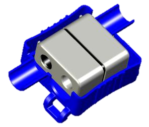
 

Figure 5: LEM patented Rogowski coil clasp


The sleeve is formed of a piece of ferrite as represented in Figure 5.

This approach was a complete success (LEM patent) – the error associated with the coil clasp has become almost negligible (Figure 6).


Figure 6: Rogowski coil accuracy comparison between a regular Rogowski coil and one using the LEM patented Rogowski coil clasp with primary conductor located at various positions inside the loop.


The accuracy is not only a question of position of the primary conductor in the loop but also of orthogonality, how the primary conductor is crossing the loop, how is it located versus the Rogowski loop axis at 90°, or 45° or 0° or 180° (Figure 7).

Here again, the ART loop is insensitive to this phenomenon and this has no impact on its accuracy thanks to the LEM know-how and patent.


Figure 7: Orthogonality effect. Primary conductor position versus the axis of the Rogowski loop.


Finally, in addition to these high performances, the product had to be easy to use, to install and adapted to any conditions of use.

The ART series provides the same ease of installation as existing split-core transformers, but with the benefits of being thinner (6.1mm diameter) and more flexible.

Whatever the chosen dimension – 35 to 300mm diameter for the coil aperture – the ART can be mounted very quickly by simply clipping it on to the cable to be measured thanks to an innovative, robust and fast twist-and-click closure method. Contact with the cable is not necessary, and the ART ensures a high level of safety as well as providing a high rated insulation voltage (1000V Cat III PD2 – reinforced) and can be used in applications requiring a protection degree up to IP57. Its fixing on the primary cable can be ensured using a cable tie through its expected slot.

The ART also allows disconnection of the coil to be detected through the use of a security seal passed through a specially designed slot, making it really useful when used with a meter (Figure 8).


Figure 8: ART mechanical features: Twist-and-click closure, security seal, and slot to attach the loop to the primary cable.


Intelligent electricity network (smart grid) applications such as power generators, home energy management (HEM), battery monitoring systems (BMS), medium voltage/low voltage substations, sub-metering, electrical vehicle stations, and solar power plants integrate more and more current sensors to ensure reliable integration of distributed renewable energy, energy storage, production and consumption. This leads to the implementation of more current sensors to allow control rooms to automate, monitor remotely and share real-time data of equipment.

With the aim to bring more harmonization in the smart grid landscape, the International Electrotechnical Commission (IEC) builds foundations in every field to provide a strong, resistant and secured electrical grid. Robust and accurate sensors in this network are major challenges to respond to this demanding environment.

IEC 61869 is the new performance standard for sensors, replacing the old IEC 60044 standard for current transformers. ART Rogowski coils sensors are designed and tested against a strict characterization test plan established by LEM experts to comply with and contribute to this evolution. Due to its strong knowledge in accurate measurement, LEM guarantees the measurement repeatability of all of its transducers and accuracy of Class 0.5 according to IEC 61869-2 for ART models for use in future smart cities and their applications.

ART series current sensors are CE marked, UL 2808 recognized and conform to IEC 61869, as well as being covered by LEM’s five-year warranty.

LEM accurate and easy-to-install smart current sensors empower the internet of energy (smart cities).

About LEM

LEM is the market leader in providing innovative and high-quality solutions for measuring electrical parameters for a broad range of applications. LEM answers the demand for an accurate, reliable and easy-to-install energy sensor for future Smart Cities.


Fonte: https://lnkd.in/dwVKAHj

maxresdefault-001

Saiba a diferença entre transdutor por Efeito Hall de Loop Aberto e Loop Fechado

O transdutor é um dispositivo que recebe um determinado sinal de entrada (Pressão, temperatura, potência, intensidade luminosa, vazão, corrente, tensão, etc.), e proporciona um sinal elétrico de saída (tensão ou corrente).

Vale destacar que o transdutor pode ser desde um dispositivo elétrico, eletrônico, térmico, mecânico e até mesmo eletromecânico.

Agora que sabemos sua função, iremos discutir um pouco sobre os transdutores de tensão e corrente.

Estes dois tipos de transdutores são ferramentas essenciais em diversos campos tecnológicos, como industrial, tração (ferroviário e subestações), automação, geração eólica e solar, e também no setor automobilístico.


Transdutores de Tensão e Corrente por Efeito Hall

O conceito mais utilizado nesses dispositivos é o Efeito Hall, descoberto no ano de 1879 pelo físico Edwin Herbert Hall, O efeito Hall é uma propriedade que se manifesta em um semicondutor inserido no “gap” de um campo magnético, gerado pela indução da corrente elétrica a ser medida. Para obter controle do processo, é inserida nesse material uma corrente de controle de tal forma que, quando a corrente elétrica a ser mensurada for zero, a tensão HALL gerada também será zero. Ao circular qualquer corrente diferente de zero, seja ela alternada, contínua, pulsada ou qualquer forma de onda, será gerado no material magnético uma Tensão Hall que será o espelho da onda que induziu esse campo. A amplitude da tensão de Hall varia com a corrente e o campo magnético.

Como o condutor irá produzir um campo magnético que varia com a corrente, é possível utilizar um sensor Hall para medir esta corrente sem interromper o circuito, sendo esta a principal vantagem da utilização deste conceito.

Transdutores por Efeito Hall são classificados em três tipos: transdutor por efeito hall de Loop Aberto (Open Loop – OL) e Loop Fechado (Closed Loop – CL) e o ETA (junção do Loop Aberto com o Fechado).


Transdutor por Efeito Hall de Loop Aberto (Open Loop – OL)

 Os transdutores de loop aberto tem um projeto mais simples do conceito de efeito Hall. Eles geralmente são de tamanhos compactos, mais leves e tem o melhor custo benefício referente à medição do parâmetro de interesse, além de ter um baixíssimo consumo de energia.


Transdutor por Efeito Hall de Loop Fechado (Closed Loop – CL)

Comparado ao transdutor de loop aberto, os transdutores de loop fechado por efeito Hall (também chamados de transdutores por efeito Hall ‘compensados’ ou de ‘fluxo zero’) possuem um circuito compensador que melhora drasticamente o desempenho, ampliando o espectro de frequência e aumentando a precisão.


Transdutores por efeito Hall ETA

A tecnologia ETA em transdutores de corrente por efeito Hall é uma patente da LEM International.

Esta tecnologia se baseia na combinação dos elementos de ambos princípios de loop aberto e loop fechado. O resultado é um dispositivo que tem o melhor balanço entre os benefícios de ambos os princípios de operação. O princípio do loop aberto é fundamentado para a medição da corrente DC e o efeito de transformador (um dos princípios do loop fechado) é usado para medir a corrente AC.

Hoje a LEM possui apenas uma série de transdutor com esta tecnologia, se trata da série LAS.


Agora que você já sabe as vantagens e desvantagens entre eles, escolha a melhor solução!


Fontes: https://www.amds4.com.br/bank/CH24101E.pdf

https://www.amds4.com.br/bank/catalogue_lem_cvt_english.pdf